

Introduction: "UVC Box" a DIY UV Sterilizer


Hey Everyone what's up!
So this is "UVC BOX" which is a low-cost easy to make UVC Sterilizer that is made for sterilizing things like Medical equipment, daily use things like smartphones, wallets, coins bills, etc.
The goal was basically to built a small low costing UVC Sterilizer from scratch.
It's low costing because I've used some generic low costing parts like a plastic container/jewelry box which can be bought for a very cheap price, I designed the housing in Fusion360 and then 3D printed it. it fits onto the lid of a plastic container perfectly.
watch the video-
Supplies
These are the parts that I used for this built-
- UVC LEDs
- Attiny84
- Copper Clad board
- 10K resistance (0805)
- A03401 MOSFET (SOT23)
- 3.7V Lithium cell (with BMS)
- LED MCPCB
- Rocker Switch SPST
- Etching powder (ferric chloride)
- 3D Printed part
- push button
- LED (0603)
- Arduino as ISP Programmer
- Plastic box/jewelry box
Step 1: Theory and Project Planning


Apparently, Irradiation with UVC light can be used to destroy microorganisms without allowing resistances to develop, and have a wavelength of around 230 nm and provide more than 1 mW of output power.
I Bought Few UVC LEDs directly from a Chinese seller (UVC LEDs are hard to find on the internet) in the 2835 package. For Testing these LEDs, I soldered them on two different PCBs which was a circular PCB with 7 LEDs and a Rectangular PCB with 10 LEDs.
However, I choose the rectangular PCB for the UVC Box as the circular PCB had 7 LEDs which means its disinfectant power would be lower than the Rectangular PCB with 10 LEDs.
For the Main Body, i choose a plactic box. i cut out a ractangular opening in its lid on which im gonna put a 3D Printed enclosure which will house the main PCB along with battery and other stuff.
Step 2: Electronics and PCB Setup


Now the main PCB of this project will be basically a Switching board in which when the button is pressed, MOSFET will turn on the UVC LED for a certain duration of time, and then the LED will turn off.
For Doing this task, I used an Attiny84 (for no special reason, any MCU can be used here).
I've attached Five small 0603 LEDs to Attiny84, Code basically turns the indicator LED on in a chaser sequence (from 1 to 5), and then we can press the button for Toggling the UVC Led, UVC Led will stay ON for around 10 minutes and then turn OFF
Step 3: Schematic and PCB Etching


After Making the schematic, I prepared a PCB and then exported its TOP Layer in Black and white as a PDF file and then printed it on glossy paper.
then I cut the FR4 board according to the Glossy paper PCB, and then added the Glossy paper PCB onto to FR4 Board and applied heat to the Glossy paper with a Cloth Iron. (This is the tone transfer process, Learn about this process from here- TONE TRANSFER) After this, I used Etching powder to etch the PCB, I drilled holes for the battery connector and header pins. after this process, I started the SMD assembly.

Step 4: PCB Assembly


I first soldered all the SMD Components one by one and then added THT Components, you can watch this whole process in the youtube video of this project.
Step 5: Flashing the Attiny84 With Arduino ISP Programmer


Now, in order to Flash the Attiny84 MCU, we need to install the Attiny core files to our Arduino IDE and then prepare an "Arduino as ISP Programmer" setup.
Now, this process is pretty long and complex, I already have made a post about this "Arduino ISP Programmer" so please check that out for a brief description.
for now, I'll show you guys the easy and short version of this whole Flashing process.
- First, download and install the Attiny core files- https://github.com/SpenceKonde/ATTinyCore
- Connect the ISP Pins of Attiny84 Board to the ISP Pins of Arduino Nano Board which is right now in the "Arduino ISP Programmer Mode"
- Go-to the Board manager and select the attiny84 as the main board.
- Change the programmer to "Arduino as ISP"
- Select the right port and hit the burn bootloader button.
- After this, open the sketch that you want to Upload in the attiny
- Go-to the sketch menu, and select "Upload using Programmer" option or just Ctrl+Shift+U
- If your wiring is perfect, then you will encounter no issue whatsoever.
Before the final assembly, I added a lithium cell and a rocker switch to this setup and tested it for the first time.
after making sure that everything is OK and working properly, I moved on to the next process which is the final assembly!
Attachments

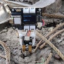
Step 6: Final Assembly and RESULT


Final Assembly is pretty simple, I glued the circuit inside the 3D printed Casing and Assemble everything together.
Here's the Result


Participated in the
Automation Contest


