pp.20-23
Nilesh Bhagat1, Paresh Jain2
1M. Tech Scholar, ECE Department, Suresh Gyan Vihar University, Jaipur, Rajasthan.
nileshbhagat42@gmail.com1
2Asst. Professor, Ph. D (P), ECE Department, Suresh Gyan Vihar University, Jaipur, Rajasthan.
jp.jpri@gmail.com2
Abstract: In this paper we have designed a CPW feed microstrip antenna at resonant frequency of 2.4Ghz. This type of microstrip antennas are of high performance, robust in design and easy to fabricate. Due to their attractive features like high rate of transfer of data wirelessly, versatility and can be designed to any geometrical shapes and compact sizes have increased their demand highly. Patch elements are placed on FR4 epoxy substrate of relative permittivity 4.4 kept at a height of 1.6mm. Simulation results are presented using HFSS version 13.0. The return loss measures -22.1, antenna gives the impedance bandwidth of 37%, VSWR observed is 1.15 and the gain proposed is 2.55 at centre frequency of 2.4 GHz.
Keywords: Microstrip antenna, CPW feed, HFSS 13.0, 2.4 GHz and FR4 epoxy.
INTRODUCTION
In the early 1970’s the first practical antenna was fabricated by Howel & Munson and microstrip antennas became popular during the 70’s period as they had the space borne applications. With the use of physical medium the long range of communication was impossible impractical so the wireless mode has enabled its use for the long range of communication with the advancement of technology better and quicker mode of communication are invented that
covers larger distances which covers the sky limits. Antennas play a vital role in communication systems to transmit and receive signals. They are versatile in geometrical dimensions and can be implemented easily. They are useful as they are of low profile, low power handling, low weight, simple and cheap [3]. Due to their attractive features like high rate of
transfer of data wirelessly and compact size have increased their demand highly and have various applications. The microstrip antennas are of very high performance, robust in design and easy to fabricate [1].
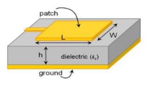
Figure 1: Microstrip Antenna
Many problems such as the surface wave excitation and narrow bandwidth are overcome by various methods such as cutting slot, increasing thickness,
etc. CPW is used in designing antenna which has low weight and low transmission losses and this method was introduced by C.P. Wen in 1969 [4]. CPW-Fed method is cheap and the line impedance and phase velocity is less dependent on substrate height then on slot width [5]. The further section of this paper presents the design, geometry and the results of the designed antenna.
ANTENNA DESIGN
The design is based on transmission line model analysis and it has rectangular patch antenna with upper pentagonal end cut with a circular cut on the ground. In the designing of antenna three basic parameters are required such as thickness of substrate, relative permittivity and dielectric substrate. Thickness of substrate reduces the size of antenna and surface radiations and low dielectric constant is preferred because the antenna gives better efficiency, low losses and higher bandwidth so, patch elements are placed on FR4 epoxy substrate of relative permittivity 4.4(low) kept at 1.6mm height. Feed line width is such that impedance is 50Ω [2]. The antenna is designed at a centre frequency of 2.4GHz.

Figure 2: Design of the proposed antenna
Table 1 The dimensions of the proposed antenna.

SIMULATION AND MEASURED RESULTS
Simulated results are obtained by using Ansoft HFSS 13.0 software. The results achieved are discussed in this section.
I. Return Loss
It is the measurement which shows that how the antenna is effective in delivering the power from the source to the antenna. Return loss measured here is −22.1 .

Figure 3: Return Loss
II. Bandwidth
S-parameter can be used in calculating the bandwidth of the antenna. The antenna gives the 10 impedance bandwidth of 37%. The frequency ranges from 1.97GHz to 2.87 GHz.
S-parameter can be used in calculating the bandwidth of the antenna. The antenna gives the 10 impedance bandwidth of 37%. The frequency ranges from 1.97GHz to 2.87 GHz.
Radiation Pattern
The radiation pattern shows the direction in which the power is directed and is also the measure which shows the radiation distribution and the power distribution in the particular direction. Radiation pattern at centre frequency 2.4GHz figure follows.

Figure 4: Radiation Pattern.
IV. VSWR
VSWR is application of the maximum and the minimum voltages at the feed line and their ratio is the VSWR showed. The value of the VSWR which is determined for perfect functioning of the antenna is that it should be less than 2. The value should be 1:1 for perfect matching and the antenna to perform efficiently. The plot shows the VSWR observed as 1.15 at 2.4Ghz.

Figure 5: VSWR

Figure 6: Smith Chart
Smith chart shows VSWR 1.15 at angle 109.23 and magnitude 0.0702 and RX is 0.9466-0.1261i which indicates that the antenna is resistive in nature.
V. Gain
Value of gain shows the amount of the power transmitted in the maximum radiation direction where the isotropic source is taken. The gain should not be less than 0dB otherwise the antenna is not radiating. We can get the gain of the antenna by the division of the radiation intensity and peak intensity. We have got the maximum gain as 2.55 at our taken frequency.

Figure 7: Gain
Parametric study on the width of feed line shows that on increasing its value, the return loss decreases and the impedance bandwidth increases.
CONCLUSION
The design is made with CPW-Fed method and the study of the result shows utmost gain calculated is 2.55 and the return loss calculated is -22.1, VSWR calculated is 1.17 and the impedance bandwidth calculated is 37% in the proposed antenna. Simulation and design of the microstrip patch antenna is done on a substrate of dielectric constant 4.4 at a resonant frequency of 2.4GHz which ranges from 1.97GHz to 2.87GHz is successfully done on HFSS. Several more designs can be simulated using different parameters gaining better results and higher efficiency finding its place in the field of wireless communication. Their main applications are in extended UTMS, WiFi, WiMax, etc
bandwidth calculated is 37% in the proposed antenna. Simulation and design of the microstrip patch antenna is done on a substrate of dielectric constant 4.4 at a resonant frequency of 2.4GHz which ranges from 1.97GHz to 2.87GHz is successfully done on HFSS. Several more designs can be simulated using different parameters gaining better results and higher efficiency finding its place in the field of wireless communication. Their main applications are in extended UTMS, WiFi, WiMax, etc.
REFERENCE
1. A.B. Mutiara, R. Refianti, Rachmansyah, “Design of Microstrip Antenna for Wireless Communication at 2.4 GHz” Journal of Theoretical and Applied Information Technology, ISSN: 1992-8645, Volume-33 No 2, p.p. 184-192, November 2011. 2. Indu Bala Pauria, Sachin Kumar, Sandhya Sharma, “Design and Simulation of E-Shaped Microstrip Patch Antenna for Wideband Application” International Journal of Soft Computer and Engineering, ISSN: 2231-2307, Volume-2, Issue- 3,p.p. 275-280, July 2012. 3. C. A. Balanis, Antenna Theory: Analysis & Design, John Willey & Sons, Inc., 1997. 4. John Wiley & Sons “Compact and Broadband Microstrip Antennas”. Kin-Lu Wong, Inc., 2002. 5. Raj Kumar, P. Malathi “On the Design of CPW- Fed Ultra Wideband Triangular Wheel Shape Fractal Antenna”, International journal of microwave and optical technology, Vol.5 NO.2, March 2010.