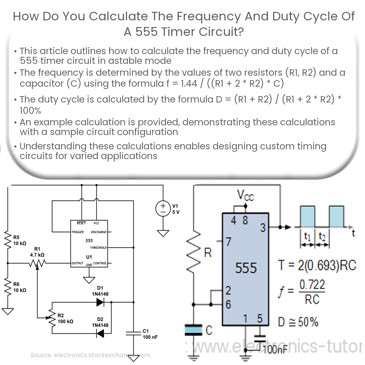
Calculate frequency with f = 1.44 / ((R1 + 2 * R2) * C) and duty cycle with D = (R1 + R2) / (R1 + 2 * R2) * 100% for a 555 timer in astable mode.
Calculating the Frequency and Duty Cycle of a 555 Timer Circuit
Calculating the frequency and duty cycle of a 555 timer circuit is essential to designing precise timing circuits. In this article, we’ll discuss the process of calculating these parameters for a 555 timer in astable mode, which is commonly used for generating square waves.
Frequency Calculation
The frequency (f) of the output waveform in astable mode depends on the values of resistors R1, R2, and capacitor C. The formula for calculating the frequency is:
f = 1.44 / ((R1 + 2 * R2) * C)
Where f is the frequency in Hz, R1 and R2 are the resistor values in ohms (Ω), and C is the capacitor value in farads (F). To calculate the frequency, simply plug in the values of the resistors and capacitor into the formula and solve for f.
Duty Cycle Calculation
The duty cycle (D) of a waveform is the ratio of the time the output signal is high (T_high) to the total period of the waveform (T). It is typically expressed as a percentage. The formula to calculate the duty cycle in astable mode is:
D = (R1 + R2) / (R1 + 2 * R2) * 100%
Where D is the duty cycle, and R1 and R2 are the resistor values in ohms (Ω). To calculate the duty cycle, insert the resistor values into the formula and solve for D.
Example Calculation
Let’s assume we have an astable 555 timer circuit with R1 = 1 kΩ, R2 = 2 kΩ, and C = 100 nF. Using the formulas above, we can calculate the frequency and duty cycle as follows:
- Frequency calculation: f = 1.44 / ((1000 + 2 * 2000) * 100 * 10-9) ≈ 240 Hz
- Duty cycle calculation: D = (1000 + 2000) / (1000 + 2 * 2000) * 100% ≈ 60%
In this example, the output waveform has a frequency of approximately 240 Hz and a duty cycle of 60%.
By understanding how to calculate the frequency and duty cycle of a 555 timer circuit, you can design custom timing circuits for various applications such as pulse generation, frequency modulation, and more.